Pie Cut for Your Thoughts?

So, the other day, I'm working on this pie cut problem. So far, I can print hundreds of these degreed pie cuts assemble them into a manifold and retrieve the data to create a 3d file which represents the mock up that I have made. But, what if, I wanted to draw up a 3d file which represented a possible manifold configuration, and then print exactly the number of pie cuts to create that specific item.
Work Flow:
Method #1
Print hundreds of various pie cuts --> Build a mockup --> Test a mock up --> Build a new mockup ... --> Convert mock up to 3d file --> ???? --> Profit.
OR
Method #2
Create a 3d file --> Print Exactly the pieces required by mockup --> Test mock up --> Adjust 3d file... --> Print difference of pieces --> ???? --> Profit.
Both of these workflows are useful. But from a Solidworks perspective the first method is much easier to accomplish. And from a time use perspective the second method saves valuable printer time and materials.
Failed attempts:
I tried assembling the pie cuts in the way that I would build a mockup. Stack the pie cuts and leave the same degrees of freedom in the mates that the real model would have. Unfortunately, Solidworks does not have friction. When I rotate one pie cut, the entire tree moves and my computer freezes for a few seconds.
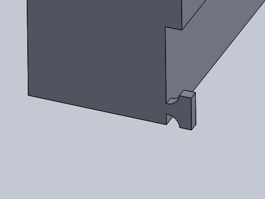
Photo Related: I then tried using a 3d sketch to define the centerline radius of my pie cut tube. This method appeared to work for a short time, but when I tried moving the tube around the arc, the tubes would collapse on each other. What I discovered is that Solidworks was playing a nasty trick on me. Instead of using a coincident mate, which I chose, it would substitute the constraints with a parallel mate. With rounding error, the 3d arc was slightly smaller than the centerline radius of the programmed pie cuts. The drawing would become over defined with the proper mates. Solidworks does not permit higher order operations to define lower order. Despite a sketch not being fully defined once out of sketch mode the dimensions of that sketch are locked.
So, what is the GOAL? To find a technique which allows the user to loosely define a path, which CAD software can solve for the constraints of the manufacturing technique.
What do I know about pie cuts?:
Pie cuts define a centerline radius which is fixed and create a junction with a maximum arc of 9 degrees or a minimum arc of 0 degrees. However, the arc created by any three pieces is only planar if the rotation angles between each pair are 0 degrees rotation, or 180 degrees. At 180 any pair is linear.
What do I know about Solidworks?:
Solidworks prefers for you to know the exact shape of objects before drawing them. Little tweaking can be performed later, and the more bodies involved the greater the tree of calculations is thus slowing the process.
The Next Step:
If I convert the definition of a pie cut method into the constraints of a 3d sketch, I believe I can make a swept boss path which is loosely defined enough to solve for my pie cuts. I have no idea how to create a rule like this in Solidworks.

Comments
Post a Comment